| Discussion (0)Milkshape toolbox - the Model tab |
| The Toolbox - Model |
The Model tab in the Toolbox is the main tool set involved in creating models. Vertices and faces are the lowest level construction tools. A selection of primitives is also included to aid the creation of models. All of the buttons on the Model panel can be clicked once to activate and clicked again to deactivate, much like an on/off button. This is the Model tab of the Toolbox, click the button you wish the see the description for: |
| Select |
Pressing the Select button (or alternatively pressing the F1 keyboard key) will reveal a selection panel below the Model panel, in this panel the user must select the type of object they wish to be able to select, as the image shows: 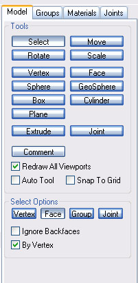 Select Tab |
| Vertex |
This sets the tool to Select Vertex mode. Vertices can be individually selected by Left-Clicking on them, or more can be selected by Left-Click-Dragging the mouse over many vertices. Multiple vertices can be selected by Shift-Left-Clicking and vertices can be deselected by Shift-Right-Clicking. In the 3D Perspective View Vertices can be selected by Alt-Left-Clicking and deselected again by Alt-Right-Clicking. The Shift operation also applies to selecting vertices in the perspective view, i.e. Shift-Alt-Left-Click and Shift-Alt-Right-Click. |
| Face |
This sets the tool to Select Face mode. Faces are selected and deselected in the same way as Vertices are with the exception that a face can only be selected in the 3D view by clicking a vertex (using Alt-Left-Click) when the 'By Vertex' option is selected. The 'By Vertex' checkbox becomes un-ghosted and available to use when the Select Face tool is selected. |
| Group |
This sets the tool to Select Group mode. Groups can be selected and deselected in the same way as for Vertices. Groups can also be selected in the perspective view by Alt-Left-Click-Dragging and deselected again by Alt-Right-Click-Dragging. |
| Joint |
This sets the tool to Select Joint mode. A joint can be selected and deselected in the same way as a Vertex. Joints can also be selected in the 3D Perspective View by Alt-Left-Click and deselected by Alt-Right-Click. |
| Ignore Blackfaces |
This option comes in handy time and time again. With this option switched off all faces behind the one the user selects will also be selected, when switched on those same faces are not selected leaving you with the face/s the user may have intended to select originally. |
| By Vertex |
This option is useful only when the tool is in Select Face mode. It allows the user to select faces not by clicking in the middle of the faces but by clicking a vertex that the face is joined to. This is used primarily in the 3D viewport where selecting a vertex selects all the faces it is attatched to. |
| Move |
This tool is used to move vertices, faces, groups and joints. The move tool only takes effect on items that are selected (i.e. highlighted red). To select the Move tool from the Model panel click the Move button or alternatively press the F2 keyboard button, Doing so will reveal the move panel, shown below. 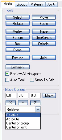 Move Tab The Move options panel allows the precise placement of selected objects. Values are typed into the three boxes at the top; the movement on that particular plane can be turned on/off by clicking the buttons below them. Depressed is off and pressed in on. When the values are keyed in the Move button is used to perform the Move action. The values in the boxes represent the amount of movement to be performed on that particular plane, not the position on that plane to move the object to. The most common way to move objects in MilkShape 3D is not though the use of this panel. In any of the three 2D views the user can Left-Click and drag the object to wherever they desire. 3D modeling is usually done in approximations but to finish a model objects may be lined up perfectly using the Move Options panel, this is rare however as a zoomed in 2D view gives adequate precision. Using such a method is also more intuitive as a response is displayed straight away whereas using the Move Options panel the move button has to be clicked before any feedback is given. |
| Rotate |
This tool is used to rotate faces, groups and joints (vertices are points in space so cannot be rotated) around the x, y and z axis. Like the Move tool, to operate on objects with this tool they must first be selected (i.e. highlighted red). This tool can be selected from the keyboard by pressing F3. The following image shows the Rotate Options panel. The panel operates in much the same manner as the Move panel; in that values are entered into the x, y and z boxes to have them rotate by that value in the designated plane. A particular plane of rotation can be turned on/off by pressing the relevant button below it. The Rotate button is pressed to rotate the object by the amounts in the boxes. With the Rotate tool there are three further, very useful options.
Center Of Mass This option is the default and most commonly used. The object will rotate about its center of mass. Origin This option makes the object rotate around the origin of the scene at point x = 0, y = 0, z = 0. This provides a distinctly different behavior from the first option. User Point This is the most flexible of the rotate options. The point for rotation is set on the Left-Click press down, any mouse movement after this rotates the object around that point. As with the Move tool, the object can also be rotated by Left-Clicking in the desired 2D viewport and dragging the mouse left and right or up and down. |
| Scale |
The scale tool is used to re-size faces and groups; it will only operate on the selected objects in the scene. The scale tool works in exactly the same way as the Rotate tool. The Center Of Mass option scales everything in on the center of the object, scaling the whole object with symmetrical proportions. The Origin option scales the object around the origin of the scene. The User Point option allows the user to select a point which to scale around. The x, y and z value boxes work in the same way as for the Move and Rotate functions. Note that the value 1.0 means Original Scale, in the same way as 0.5 is half the Original Scale and 2.0 is double the Original Scale. I only say this to highlight the fact that zero is not the original scale, if you scale anything by zero; it will be non existent, in the same way as if you multiply any number by zero. |
| Vertex |
Selection of the vertex tool (achievable on the keyboard by pressing F5) does not reveal any option panels. This tool is all encompassing as it deals only with the placement of vertices in any of the 2D viewports. Simply Left-Click where the vertex is to be placed. The vertex will always be placed on the zero point of one of the axis, for example if you are placing a vertex on the (front) x-y plane then the z position of that vertex will be zero. |
| Face |
The Face tool allows the creation of polygons (particularly triangles) between specified vertices. The tool can be selected on the keyboard by pressing F6. The following image shows the Face Options panel. The threshold value represents the proximity the mouse cursor has to be in to successfully select the vertex as the next vertex to assemble a face. To create a face three vertices must be selected in order. The order in which they are selected is important as it defines wither the face will face outwards or inwards. Select vertices in an Anti-Clockwise direction to create an outwards facing face. A good way to see if a face is outwards or inwards facing is to right click in the perspective viewport and select Flat Shaded from the pop-up menu. If any faces are black then this means they are inwards facing. |
| Primitives |
| Sphere |
One of the in-built primitives, the sphere tool is used to create a sphere of Slices by Stacks size. The Slices value represents the number of cuts on the x axis, the Stacks the number of cuts on the y axis. The more of each you choose the smoother the Sphere will be. It is best to keep the number of Stacks at half the number of Slices if you want a sphere, however alterations can produce interesting results. When the sphere tool is selected, to create a sphere just Left-Click in one of the 2D viewports and drag the mouse until the Sphere is the desired size. |
| GeoSphere |
A more optimised version of the original sphere, a GeoSphere of the same visual detail uses less faces than a Sphere. The depth value acts as a multiplier for the amount of faces wanted. To create a GeoSphere just Left-Click in one of the 2D viewports and drag the mouse until the GeoSphere is the desired size. |
| Box |
Upon Selection the box tool does not reveal any options panels. The box tool is fairly self-explanatory. Left-Click in any of the 2D viewports to start the box then drag to the opposite corner to complete the creation of the box. The sides of a newly created box will all be equal, i.e. it will be a cube. |
| Cylinder |
The Cylinder tool works in much the same way as the sphere tool. Stacks and Slices define the detail of the Cylinder. The Cylinder has an extra option, which is Close Cylinder. If it is unselected then the Cylinder will not have caps on either end, i.e. it will be open. To create a Cylinder (closed or not) just Left-Click in one of the 2D viewports and drag the mouse until the Cylinder is the desired size. |
| Extrude |
The Extrude operation can only be carried out on faces. Extruding vertices results in a mess as a point in space cannot be extruded. Selection of one or more faces is necessary to successfully extrude something. After selecting the faces to be extruded then the selection of the extrude tool Left-Click and drag in a 2D viewport in which you can see the height of the extruded section. Precision extruding can be achieved by using the x, y and z plane value boxes. As surfaces are commonly extruded in only one direction, you will predominantly use only one box. The Auto Smoothing Group option will smooth shade the polygons after extrusion has been completed. |
| Joint |
Upon Selection the joint tool does not reveal any options panels. Simply Left-Click in a 2D viewport to place a joint. One thing to remember when placing a joint is the hierarchy of the skeleton you are creating. A newly placed joint will be selected meaning the next joint will be connected by a Bone to the last created one. In a human skeleton, for example, the pelvis is joined to two legs, so in order to represent this is MilkShape 3D the pelvis joint would be placed, then the joint for one of the hips. Next, the pelvis joint would have to be selected in order to place the hip joint for the next leg. This is explained in more detail in the Animation Tutorial. |
| Redraw All Viewports |
Having this checkbox checked will force all the viewports to be redrawn when performing operations. With this unchecked viewports only update when they are clicked on. For example with Redraw All Viewports checked a move operation would force the viewports to continuously update with the new position of the moved object, but with it unchecked the viewports would only update when the move operation has finished, i.e. when the mouse button is released. |
| Auto Tool |
This option can be used to automatically switch back to the last tool you were using. For example if you wanted to select vertices individually for movement, check the Auto Tool option, then the Select tool, Select the vertex to be moved then click the move tool. After the move operation is completed the Auto Tool will switch the current tool back to Select, once the select operation is complete it will switch back to Move, etc... This is an alternative option for tweaking, but it is best to get used to using the function keys at the top of your keyboard, they allow more flexibility. |
| Categories |
| Editor Bar |
 Versions
 Last changes
 All articles
 Categories